CHAPTER TITLE: Approaches
Below is a list of the figures (diagrams, charts, and pictures) from the IPH Chapter 4. They are listed in the order they are found in the Instrument Procedures Handbook.
AUDIO RECORDING
FIGURE 4-1
Chippewa Regional Airport (KEAU), Eau Claire, Wisconsin.

FIGURE 4-2
Construction of circling approach area.

FIGURE 4-3
Instrument approach chart.

FIGURE 4-4
Procedure identification.

FIGURE 4-5
Multiple approaches.

FIGURE 4-6
Procedures with circling landing minima.

FIGURE 4-7
Durango approach and low altitude en route excerpt.

FIGURE 4-8
Cheyenne Regional (KCYS), Cheyenne, Wyoming, ILS or LOC RWY 27.

FIGURE 4-9
Fly-by and fly-over waypoints.

FIGURE 4-10A
View during an approach with EFVS (left) and without EFVS (right). (Images courtesy of NASA Langley Research Center).

FIGURE 4-10B
EFVS Operation to Touchdown and Rollout.

FIGURE 4-10C
EFVS Operations to 100 Feet Above the TDZE.

FIGURE 4-11A
VNAV information.

FIGURE 4-11B
Descent Angle N/A.

FIGURE 4-12
RNAV GPS approach minima.

FIGURE 4-13
GBAS architecture.

FIGURE 4-14
GLS approach at Newark, New Jersey.

FIGURE 4-15
RNAV RNP approach procedure with curved flight tracks.

FIGURE 4-16
North Platte Regional (KLBF), North Platte, Nebraska, RNAV (GPS) RWY 30.

FIGURE 4-17
Example of LNAV and Circling Minima lower than LNAV/VNAV DA. Harrisburg International RNAV (GPS) Runway 13.

FIGURE 4-18
Explanation of Minima.

FIGURE 4-19
Airport sketch and diagram for Chicago O'Hare International.

FIGURE 4-20
Example approaches using autopilot.

FIGURE 4-21
Determination of visibility minimums.

FIGURE 4-22
RNAV approach Fort Campbell, Kentucky.

FIGURE 4-23
Orlando Executive Airport, Orlando, Florida, ILS RWY 7.

FIGURE 4-24
Missed approach procedures for Dallas-Fort Worth International (DFW)4.

FIGURE 4-25
Missed approach point depiction and steeper than standard climb gradient requirements.

FIGURE 4-26
Two sets of minimums required when a climb gradient greater than 200 ft/NM is required.

FIGURE 4-27
Example of approach chart briefing sequence.

FIGURE 4-28
Approach segments and obstacle clearance.

FIGURE 4-29
Feeder routes.

FIGURE 4-30
Terminal routes.

FIGURE 4-31
DME arc obstruction clearance.
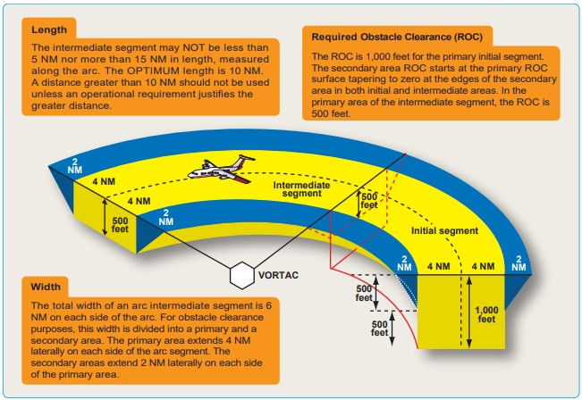
FIGURE 4-32
Course reversal methods.

FIGURE 4-33
Procedure turn obstacle clearance.

FIGURE 4-34
Approach without a designated IF.

FIGURE 4-35
Charted visual flight procedures (CVFP).

FIGURE 4-36
Terminal arrival area (TAA) design “basic T.”

FIGURE 4-37
RNAV approaches with and without TAAs.

FIGURE 4-38
Traditional GPS approach overlay.

FIGURE 4-39
Lincoln Muni KLNK Lincoln, Nebraska, RNAV GPS RWY 14 approach.

FIGURE 4-40
ILS final approach segment design criteria.

FIGURE 4-41
ILS approach categories.

FIGURE 4-42
Category III approach procedure.

FIGURE 4-43
Classification of Simultaneous Parallel Approaches.

FIGURE 4-44
Sacramento International KSMF, Sacramento, California, ILS or LOC RWY 16L.

FIGURE 4-45
Charlotte Douglas International KCLT, Charlotte, North Carolina, ILS or LOC RWY 18L.

FIGURE 4-46
Simultaneous Independent Approach Example Using ILS Approaches.

FIGURE 4-47
Simultaneous independent close parallel approach example using ILS PRM approaches.

FIGURE 4-48
Example of Simultaneous close parallel instrument approach: Atlanta, Georgia, ILS PRM RWY 10 and AAUP.

FIGURE 4-49
Example of Approach and AAUP used for Simultaneous Offset Instrument Approach Procedure.

FIGURE 4-50
Converging approach criteria.

FIGURE 4-51
Dallas-Fort Worth KDFW, Dallas-Fort Worth, Texas, CONVERGING ILS RWY 35C.

FIGURE 4-52
Fort Rucker, Alabama, KOZR VOR RWY 6.

FIGURE 4-53
Alexandria International (AEX), Alexandria, Louisiana, KAEX VOR DME RWY 32.

FIGURE 4-54
Carthage/Panola County-Sharpe Field, Carthage, Texas, (K4F2), NDB RWY 35.

FIGURE 4-55
Tucson/Ryan Field, Tucson, Arizona, (KRYN), NDB/DME or GPS RWY 6R.

FIGURE 4-56
Asheville Regional KAVL, Asheville, North Carolina, radar instrument approach minimums.

FIGURE 4-57
PAR final approach area criteria.

FIGURE 4-58
Vicksburg Tallulah Regional KTVR, Tallulah Vicksburg, Louisiana, LOC RWY 36.

FIGURE 4-59
Vicksburg Tallulah Regional KTVR, Tallulah Vicksburg, Louisiana, LOC RWY 36.

FIGURE 4-60
Dayton Beach International DAB, Dayton Beach, Florida, LOC BC RWY 25R.

FIGURE 4-61
Hartford Brainard KHFD, Hartford, Connecticut, LDA RWY 2.

FIGURE 4-62
Lebanon Floyd W Jones, Lebanon, Missouri, SDF RWY 36.
